Hydro Air System Diagram
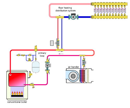
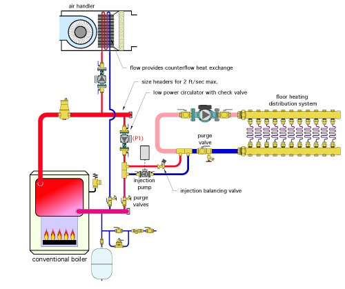
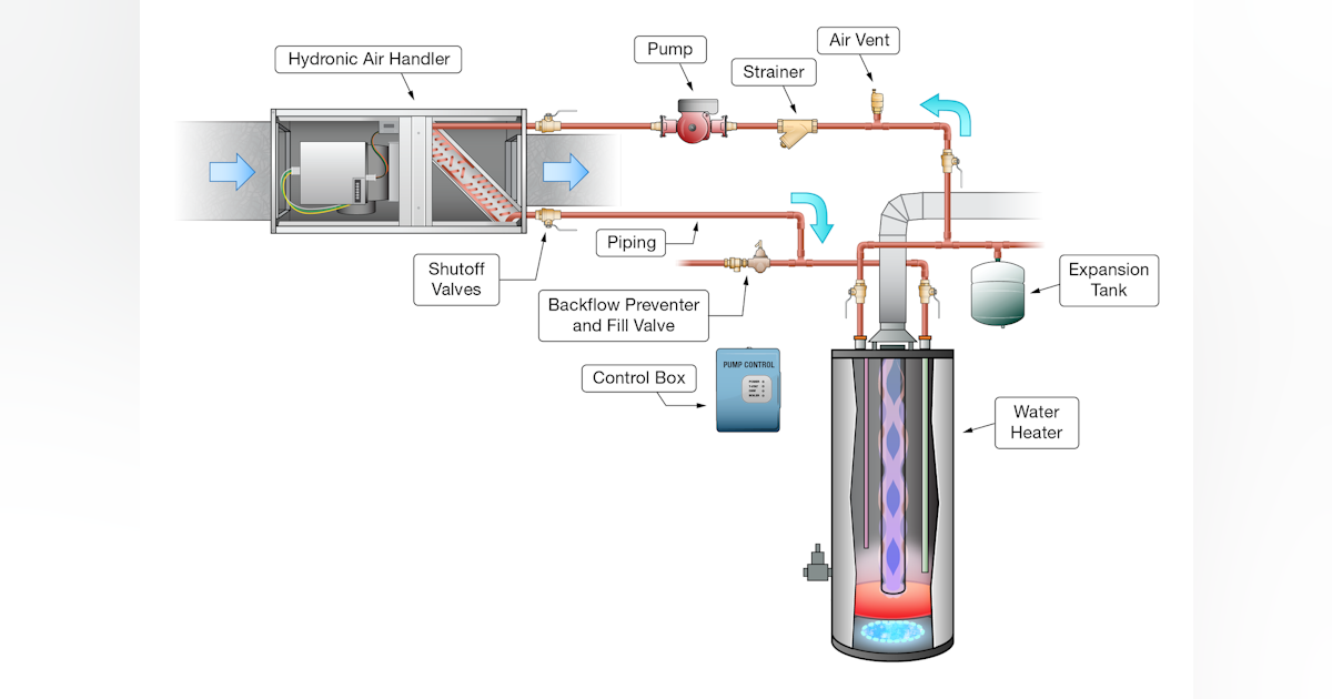
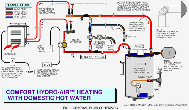
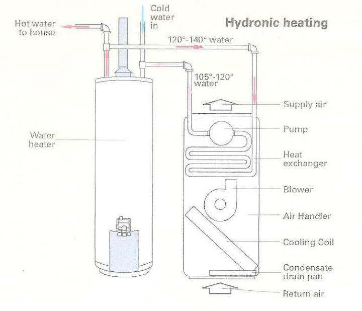
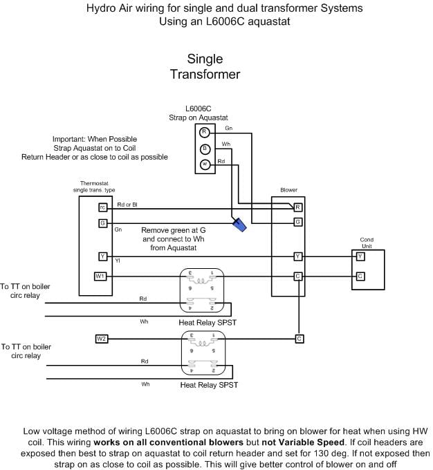
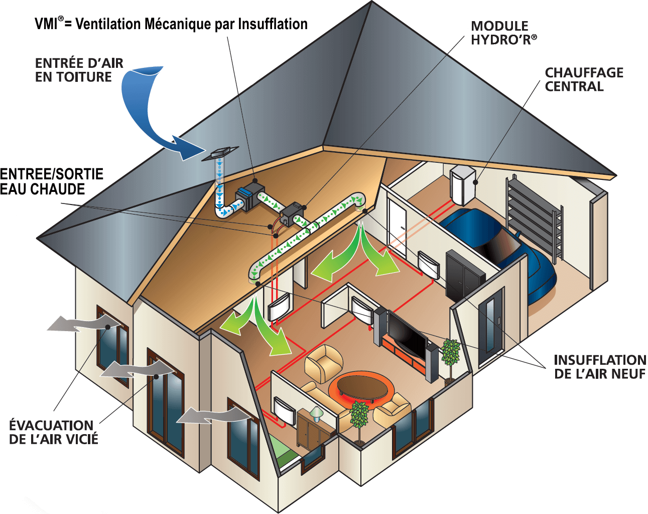
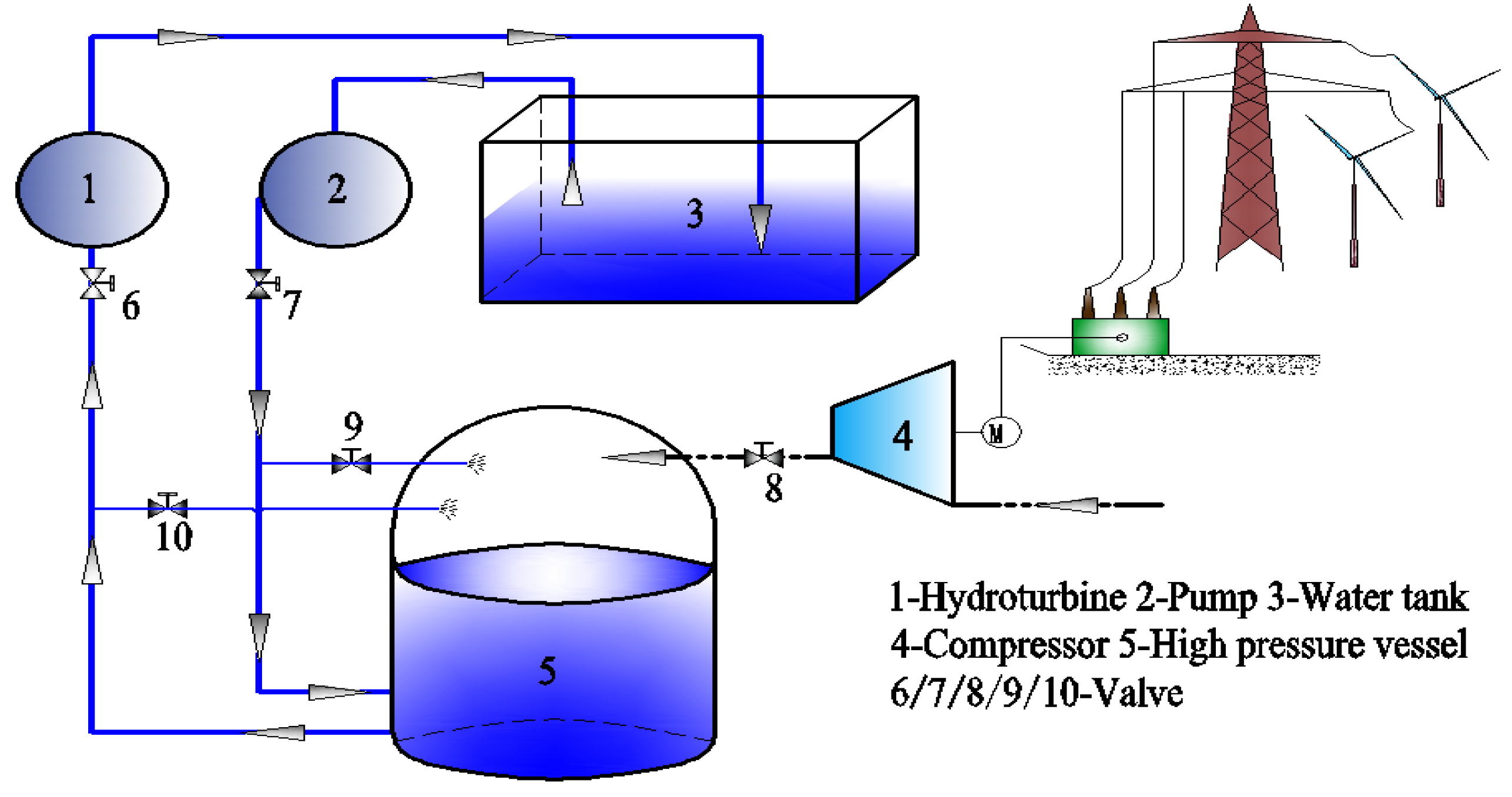
Hydro air system diagram. It is impossible to compress water so we provide the compressed air as a spring which will always press up the water in hydrophore tank and maintain the system pressure. A Hydro-Air system is a combination of a hot water and a hot air system. This is a PID controller.
The liquid-level switch senses the. Working Of hydrophore tank Let me explain the working of hydrophore tank in simple terms. Wire Diagram for Taco Zone Valves Taco Zone Sentry Zone Valves provide on-off normally open or normally closed control in both open and closed hydronic systems.
A hot water boiler either oil or gas fired generates heat. However with more drippers more can go wrong. Average summer temperatures in the state range between.
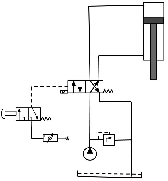
These features may be together inside a cover mounted on top of the tank or installed separately. The valves can be used in a wide variety of heating and non-condensing cooling applications primarily designed for use with baseboard fan coils radiators convectors air handlers heat pumps and radiant applications. Reading fluids circuit diagrams - hydraulic pneumatic symbols.
Here is a simple diagram of ship hydrophore system. The tankless water heater acts as the heat source for air thus meeting both hot water and heating demands for the home simultaneously said Shaun Thomas hybrid applications engineer Rheem Mfg. Later in this article series we will describe some simple hydraulic and pneumatic circuits composed of these circuit elements.
Add to Wish List. The air handler blower motor then distributes the warm air through the duct system and into the living space. 10-4861 Hydro Air Magna Directional Jet.
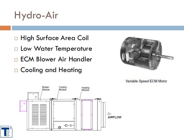
8 NEW SMART PUMPS Speed varies without sensors High Efficiency ECM zElectronically Commutated Motor zAka. GE has the capability to design and manufacture electrical machines for the most stringent application requirements.
Hydro is a leading industrial company committed to a sustainable future.
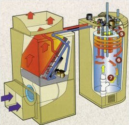
The air handler blower motor then distributes the warm air through the duct system and into the living space. This is a PID controller. Hydraulic Separator with airdirt media Hydraulic Separator. A drip hydroponic system involves the nutrient solution being pumped through a tube above the plants which drips the solution down onto the plant and roots. Reading fluids circuit diagrams - hydraulic pneumatic symbols. 265 Escutcheon Polished Chrome 10-2155 2899 32 Hydro Air Air Control 12in 175in OD Bone 10-2200 2495 1697. 50 60 Hz. 2000 37500 kVA Speed. A hydro-air system features an air handler that has an additional coil installed which is heated by water from the boiler.
Examples of Analogue electronic type hydraulic governor are as follow and a typical block diagram is shown in figure 63. We have an interesting snow removal system its called July. A Hydro-Air system is a combination of a hot water and a hot air system. A drip hydroponic system involves the nutrient solution being pumped through a tube above the plants which drips the solution down onto the plant and roots. 3000 13800 Volts Frequency. 10-4861 Hydro Air Magna Directional Jet. The air handler blower motor then distributes the warm air through the duct system and into the living space.













Post a Comment for "Hydro Air System Diagram"